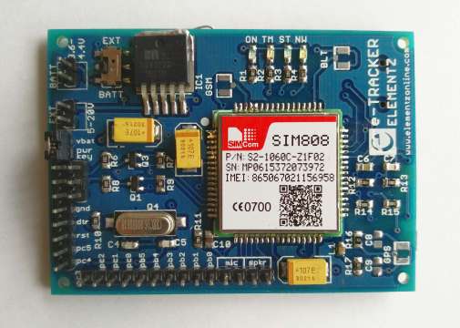
The e-Tracker from Elementz features an ATmega328 and SIM808 which provides the flexibility of arduino along with the added features of SIM808 which has GSM,GPS and bluetooth functionality.
SIM808 module is a complete Quad-Band GSM/GPRS module which combines GPS technology for satellite navigation.
The compact design which integrated GPRS and GPS in a SMT package will significantly save both time and costs for customers to develop GPS enabled applications. Featuring an industry-standard interface and GPS function, it allows variable assets to be tracked seamlessly at any location and anytime with signal coverage.It has high GPS receive sensitivity with 22 tracking and 66 acquisition receiver channels. Besides, it also supports A-GPS that is available for indoor localization. The module is controlled by AT command via UART and supports 3.3V and 5V logical level. You can buy it from here.
Features
- Quad-band 850/900/1800/1900MHz
- GPRS multi-slot class12 connectivity: max. 85.6kbps(down-load/up-load)
- GPRS mobile station class B
- Controlled by AT Command (3GPP TS 27.007, 27.005 and SIMCOM enhanced AT Commands)
- Supports Real Time Clock
- Supply voltage range 5V ~ 12V
- Integrated GPS/GNSS and supports A-GPS
- Supports 3.0V to 5.0V logic level
- Low power consumption, 1mA in sleep mode
- Supports GPS NMEA protocol
- Standard SIM Card

Powering the module
Firstly insert the SIM card in the sim holder. Make sure to use a normal SIM card (Micro or nano SIM cards can be used with the help of sim card adapter.)
You can power the board from a power adapter(9V/12V – 1A). Make sure the toggle switch is in EXT position. Connect it to the EXT terminals.
You can also power the board from battery. Make sure the toggle switch is in BAT position. And connect a 3.7V (3.6V – 4.4V) Lipo battery to the BATT terminals.
Also there is a battery charger on board. So you can connect a power adapter and battery. The board will be powered by the battery while it is simultaneously charged. Make sure the toggle switch is in BAT position.
Programming the Board.
The board has an Atmega328 on board based on the Arduino UNO. You can program it using using Arduino IDE. Select Arduino UNO from the Tools –> Board –> Arduino UNO. Now you need a FTDI/CP2102 USB to UART converter/adapter to program the board. Connect it to the computer. Select the COM port. Connect the RX of the USB to UART converter to the Hardware TX of the board and vice versa. Connect VCC and GND. Connect DTR of the converter to DTR of the board. Now you are all set.
An Alternative to Arduino IDE is the PlatformIO IDE. It is a next-gen IDE for IOT with Cross-platform build system and intelligent code completion.
Using the board as a Standalone one.
Short the terminals by using jumpers. Now the uart of SIM808 and ATmega328 are connected. Now the MCU and GSM will communicate via uart.
Using only the SIM808 functionalities.
If you want to use only the SIM808 functionalities, you can do so by connecting to the Rx and Tx pins of the SIM808 on the board. Click here to know more about interfacing with a computer. To check the GSM module we have made a GSM Test Utility.


